Homework 2
(c) 2019 Justin Bois and Michael Elowitz. With the exception of pasted graphics, where the source is noted, this work is licensed under a Creative Commons Attribution License CC-BY 4.0. All code contained herein is licensed under an MIT license.
This document was prepared at Caltech with financial support from the Donna and Benjamin M. Rosen Bioengineering Center.

This homework was generated from a Jupyter notebook. You can download the notebook here.
2.1: Design principles for toggles, 30 pts
Consider two components, A and B, which regulate each other. A may activate or repress B, and B may activate or repress A. There are three possible architectures in this scenario, two with positive feedback and one with negative feedback, shown below.
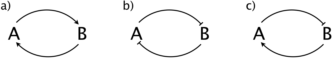
a) A circuit can behave like a toggle if it has two stable steady states, one with A high and B low and another with B high and A low. Only one of the above architectures can function as a toggle. Which one? Explain in words and sketches why only the one you chose can be a toggle.
b) A and/or B may have ultrasensitive regulation, which we describe with a Hill coefficient, $n$, greater than one. Show that without ultrasensitive regulation, even the architecture you chose cannot have toggle behavior.
2.2 Autoregulation in a C1-FFL, 40 pts
This problem is based off of problem 4.3 from Alon's book. The type 1 coherent feedforward loop (C1-FFL) is another motif that is found in large numbers in naturally occurring networks. In the figure below, we show two C1-FFL networks in which the regulator Y is autoregulated. In the C1-FFL with AND logic, Y shows autorepression, and in the C1-FFL with OR logic, it shows autoactivation. These "decorations" on C1-FFLs often occur in nature.
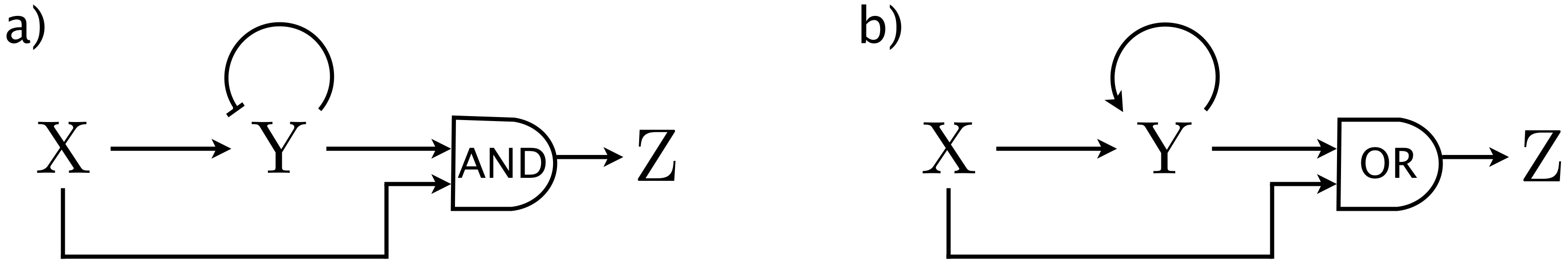
a) As we learned in lecture, the C1-FFL with AND logic shows sign-sensitive delay. Specifically, if X is suddenly turned on, the response of Z is delayed, but if X is suddenly turned off, the response of Z is instantaneous. Analyze the left circuit in the above figure, and compare its dynamics to the canonical C1-FFL circuit with AND logic. Specifically address how the delay time changes. Assume that the regulation of Y follows AND logic.
b) The C1-FFL with OR logic also shows sign-sensitive delay. With OR logic, though, there is no delay when X is suddenly turned on, but rather delay when X is suddenly turned off. Analyze the right circuit in the above figure and compare its dynamics to the canonical C1-FFL circuit with OR logic. Again, address how the delay time changes, this time assuming that the regulation of Y follows OR logic.
2.3: A tri-stable cell-fate determinant circuit, 30 pts
Common myeloid precursor (CMP) cells are stem cells that can either differentiate into an erythroid (red blood cell) cell or a myeloid (bone marrow) cell. Such a binary differentiation may be regulated by a genetic circuit akin to the toggle circuit we have studied in class. However, the progenitor state of the CMP cells is also stable, which suggests tristability of the underlying circuit. In particular, the transcription factors GATA1 (which we will call X for convenience) and PU.1 (which we will call Y) are mutually repressive, which gives them the toggle-like behavior. They also are autoactivating. These interactions are summarized in the circuit below.
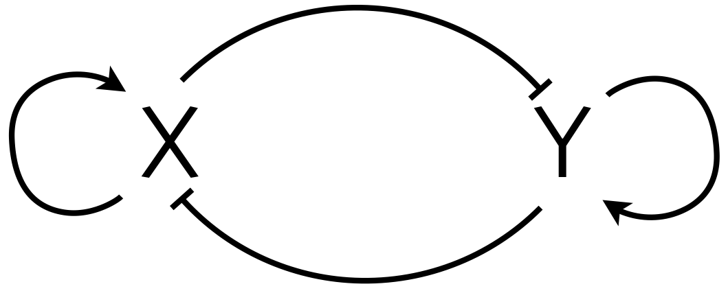
Huang and coworkers (Dev. Biol., 2007) claimed that adding the autoactivation to the mutually repressive toggle can give tristability. Your task is to assess that claim. Model the circuit where the repression of X by Y and X's autoactivation exhibit OR logic as does repression of Y by X and Y's autoactivation. Can you come up with parameter values that show tristability?
We have not covered some of the mathematical techniques, such as linear stability analysis, that help test the stability of fixed points. However, the graphical nullcline analysis we have covered is useful and sufficient to demonstrate tristability. Think about how many fixed points are necessary to get tristability.